Published by Christopher J. Holley | Mopar History & Tech | February 2026
Inside the Car’s Digital Nervous System: Understanding CAN Bus
Step inside a modern car, and you will find it is far more than steel, rubber, and gas; it is a finely tuned network of electronic brains talking to each other at lightning speed. This invisible network is called the CAN bus, short for Controller Area Network, and it is the silent hero behind every smooth gear shift, precise brake response, and responsive dashboard gauge.
At its core, the CAN bus is a high-speed communication system connecting dozens of electronic control units, or ECUs. From the engine control module (ECM) and transmission to ABS brakes, airbags, and even your infotainment screen, nearly every component relies on CAN to stay in sync. Imagine dozens of tiny computers, all chatting over a single pair of wires, without the chaos of a spaghetti junction of circuits.
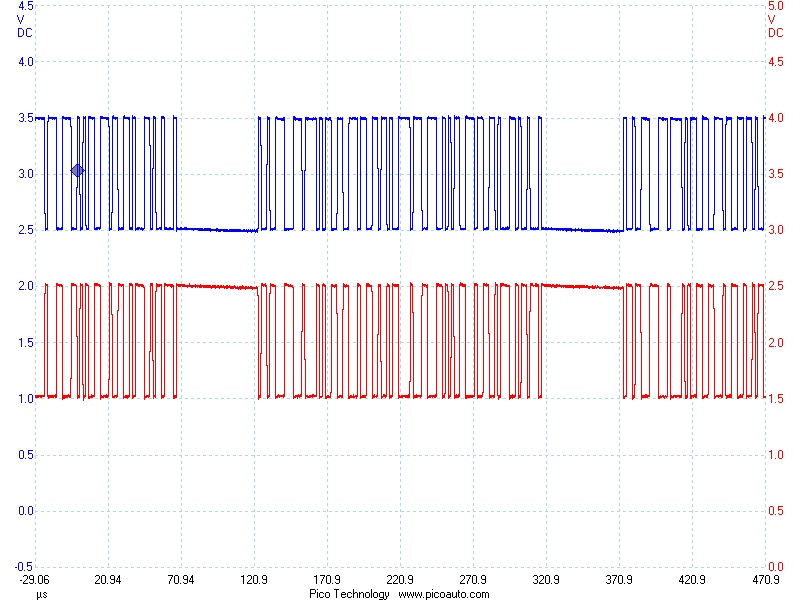
The secret lies in simplicity: a differential pair of wires, known as CAN High and CAN Low. These two strands carry signals as voltage differences, allowing the system to shrug off the electrical noise of a roaring engine or flashing headlights. A logical zero, called dominant, is a clear voltage difference between the two wires; a logical one, or recessive, is when the voltages are almost equal. This clever setup ensures the bus remains fast, reliable, and collision-free.
Every piece of information on the CAN bus is packaged into a message frame, an electronic envelope that includes a unique ID, the data itself, error-checking codes, and acknowledgments from other modules. The ECM might send a frame reading, “Engine RPM: 3200,” and every other ECU that needs that information can read it in real time. Even when multiple modules talk at once, the system’s prioritization ensures critical messages always get through first.
There are a few flavors of CAN in the automotive world. High-speed CAN, running up to 1 Mbps, handles engine, transmission, and braking systems where milliseconds matter. Low-speed or fault-tolerant CAN, slower but resilient, manages comfort and convenience features like windows, locks, and lights. The latest CAN FD standard increases data payloads, keeping pace with the growing demands of modern vehicles.
Why does it matter? CAN dramatically reduces wiring complexity, enhances reliability, and lets manufacturers add new features without a complete electrical overhaul. Press the brake pedal, and the sensor’s signal travels over the CAN bus: the ABS module engages, the ECM adjusts torque, and the transmission responds, all in the blink of an eye.
The next time you slide behind the wheel, remember beyond the roar of the engine and the shine of polished paint lies a sophisticated digital network orchestrating every action. The CAN bus is not just wiring, it is the car’s nervous system, keeping everything in perfect harmony.
Bit Stuffing on CAN Bus
Bit stuffing is the mechanism of inserting one or more non-information bits into a message to be transmitted, to break up the message sequence, for synchronization purpose.
Purpose of Bit Stuffing
In Data Link layer, the stream of bits from the physical layer is divided into data frames. The data frames can be of fixed length or variable length. In variable – length framing, the size of each frame to be transmitted may be different. So, a pattern of bits is used as a delimiter to mark the end of one frame and the beginning of the next frame. However, if the pattern occurs in the message, then mechanisms need to be incorporated so that this situation is avoided.
The two common approaches are −
- Byte – Stuffing − A byte is stuffed in the message to differentiate from the delimiter. This is also called character-oriented framing.
- Bit – Stuffing − A pattern of bits of arbitrary length is stuffed in the message to differentiate from the delimiter. This is also called bit – oriented framing.
Frame in a Bit – Oriented Protocol
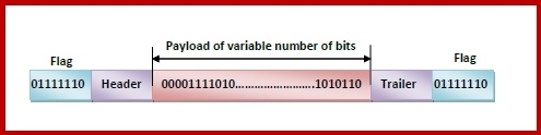
In bit-oriented protocols, the message is coded as a sequence of bits, which are interpreted in the upper layers as text, graphics, audio, video etc. A frame has the following parts −
- Frame Header − It contains the source, and the destination addresses of the frame.
- Payload field − It contains the message to be delivered.
- Trailer − It contains error detection and error correction bits.
- Flags − A bit pattern that defines the beginning and end bits in a frame. It is generally 8-bits. Most protocols use the 8-bit pattern 01111110 as flag.
Bit Stuffing Mechanism
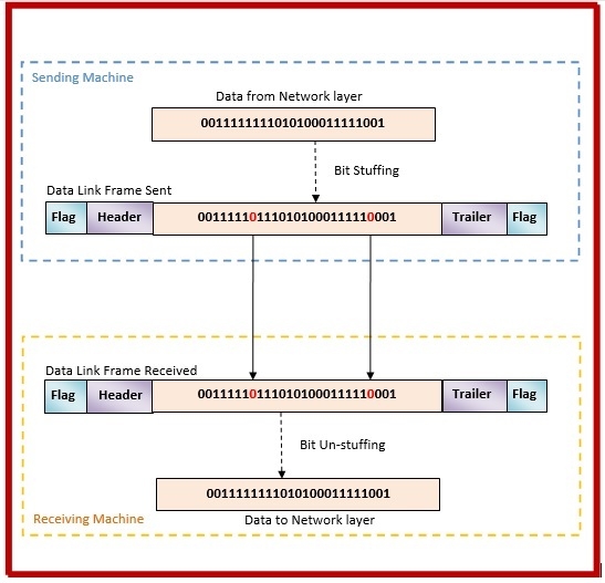
In a data link frame, the delimiting flag sequence generally contains six or more consecutive 1s. To differentiate the message from the flag in case of the same sequence, a single bit is stuffed in the message. Whenever a 0 bit is followed by five consecutive 1 bits in the message, an extra 0 bit is stuffed at the end of the five 1s.
When the receiver receives the message, it removes the stuffed 0s after each sequence of five 1s. The un-stuffed message is then sent to the upper layers.
CAN FD: The High-Speed Backbone of Modern Vehicles
Modern vehicles are no longer simple mechanical machines. They are intricate networks of electronic control units, or ECUs, communicating constantly to manage everything from engine performance to braking, infotainment, and advanced safety systems. At the center of this electronic ecosystem is the Controller Area Network, or CAN bus. As vehicles become more sophisticated, the original CAN standard is no longer sufficient to handle the growing flow of data. This is where CAN FD, or Flexible Data-rate CAN, comes into play.
The Need for CAN FD
Classic CAN, introduced in the 1980s, is a robust and reliable communication protocol. It can transmit up to eight bytes of data per message at speeds of up to one megabit per second. This was adequate for the relatively simple electronic systems of earlier vehicles. Modern cars, however, feature advanced driver-assistance systems, high-definition infotainment, and electric or hybrid powertrains, all of which require vastly more data to travel across the vehicle network. CAN FD was developed to carry larger amounts of data at higher speeds while remaining compatible with existing CAN networks.
Key Features of CAN FD
- Flexible Data Length – CAN FD can transmit up to sixty-four bytes per frame, eight times the payload of classic CAN. This allows complex data to move efficiently across the network with fewer messages.
- Flexible Data Rate – While the arbitration phase of a message follows the rules of classic CAN, the data phase can be transmitted at higher speeds, often five to eight megabits per second.
- Backward Compatibility – CAN FD can coexist with classic CAN nodes. Manufacturers can upgrade networks incrementally without replacing every existing module.
- Enhanced Error Checking – CAN FD employs a larger cyclic redundancy check (CRC) to ensure that longer messages are transmitted reliably and without corruption.
How CAN FD Works
A CAN FD frame closely resembles a classic CAN frame. The primary differences are a larger data field and a higher transmission speed during the data phase. Critical messages still follow standard arbitration rules, ensuring proper priority handling, while larger, non-critical data moves swiftly across the network.
Why CAN FD Matters
Modern vehicles generate an unprecedented volume of data. CAN FD is essential to keep this information flowing smoothly:
- Advanced Driver-Assistance Systems (ADAS) – Cameras, radar, and LiDAR sensors produce massive amounts of data that must be transmitted in real time to maintain safety and performance.
- Infotainment Systems – High-definition audio and video streams require larger, faster messages to maintain quality and responsiveness.
- Electric and Hybrid Powertrains – Battery management, electric motors, and regenerative braking systems rely on rapid, reliable communication for efficiency and safety.
In essence, CAN FD is the evolution of classic CAN, providing higher capacity, higher speed, and improved reliability to meet the demands of modern, connected vehicles. It ensures that every sensor, actuator, and control module communicates effectively, keeping the car responsive, safe, and intelligent.
Classic CAN vs. CAN FD: A Quick Comparison
| Feature | Classic CAN | CAN FD |
| Maximum Data per Frame | 8 bytes | 64 bytes |
| Data Rate | Up to 1 Mbps | Up to 5–8 Mbps (data phase) |
| Arbitration Phase Speed | Same as data rate | Same as classic CAN (fixed speed) |
| Error Checking | Standard CRC | Larger CRC for enhanced reliability |
| Typical Applications | Engine, transmission, ABS, airbags | Advanced driver-assistance systems, high-definition infotainment, electric/hybrid powertrains |
| Backward Compatibility | N/A | Compatible with classic CAN nodes |
| Benefits | Reliable, proven, low complexity | High-capacity, high-speed, future-proof |
Key Takeaway:
Classic CAN excels at transmitting small, critical messages in real time. CAN FD expands capacity and speed for modern vehicles, handling large data streams from sensors, infotainment, and electric powertrains while maintaining backward compatibility.

Leave a comment